Sabtu, 19 Februari 2022

central electric heat wiring

Room thermostat installation wiring guide. Electric radiant heating systems buried within thermal masses such as between cement board and ceramic tile can retain heat for a long time even after the power is turned off.


Bunch Ideas Of Wet Underfloor Heating Wiring Diagram And Central S Plan Heating Systems Central Heating System Thermostat Wiring

Operation - Hot water and central heating.

. Gather in a central room where there. Is a Touchstone Energy Cooperative and provides electric power to over 4800 farm residential and commercial consumer-members in southeastern South Dakota including Aurora Brule Buffalo Davison Hanson Jerauld Miner and Sanborn counties. Call 702-279-6040 or Request A Free Quote Online.

It can cool 1600-2000 sqft. 16 - 195 SEER MULTI-STAGE VARIABLE SPEED. Here power is also applied to programmer terminal 4 which connects via wiring centre terminal 4 to the room thermostat.

Once the valve is fully open a switch inside connects the grey and orange wires together. Dont worry about the word emergency think of it as auxiliary heat which is the gas furnace. And costs 3500-4300 includes installation.

Try not to route cables through insulation and NEVER if the insulation is Polystyrene this will. During an outage turn off appliances that use lots of energy such as air conditioners. Complete Split Systems IndoorOutdoor Air Conditioner Electric Heat Strip.

South Central Indiana Rural Electric Membership Corporation SCI REMC was established in 1939 and is the largest rural electric cooperative in Indiana. Higher temperatures reduce the current carrying capabilities of cables. Electric radiant floor systems offer a discreet way of heating a floor.

Never route cables near sources of heat such as central heating pipes or hot water pipes the extra heat could damage the cable but also impede its ability to carry the full load of the shower without suffering damage. If heat is required power continues to terminal 5 in the wiring centre and therefore to the white valve wire. Central Electric Cooperative Inc.

Manufactured by Rheem Goodman Diamondair Mitsubishi Bard Daikin Gree Grandaire and many more. Penny Electric offers Residential Commercial Electrician Services in the Las Vegas Henderson NV areas. These systems are brand new and carry the full factory warranty.

Most heat pumps have electric heat backup but this only comes on when the heat pumps go into the defrost cycle or when the temperature gets really cold outside and the heat pump cant keep up with the load with the load being the heat loss from your home. Central heating can heat a 1000 square yard home but a single electric fireplace can heat up just a simple 400 sq ft room. Because water conducts heat away from the body bathing in tepid water is a good cooling technique.

15 - 16 SEER VARIABLE SPEED. Available at our Jacksonville and Melbourne branches. Electric floor systems work just like an electric blanket.

The 4 to 5 Ton 18 SEER MrCool Universal Central Heat Pump Split System is one of the most high performing versatile and simple heating and cooling products available from the industry today. Central Air and Heat Pumps. Central heating is of course preferable to an electric fireplace which heats a single room.

Power starts at terminal 4 CH On in the programmer. Electrical wiring is an electrical installation of cabling and associated devices such as switches distribution boards sockets and light fittings in a structure. After Hours Will Call Box.

Keep the doors of your refrigerator and freezer shut to keep the cold in. If heat is required power continues to terminal 5 in the wiring centre and operates the motor in the central heating valve. Allowable wire and cable types and sizes are specified according to the circuit operating voltage and electric current capability with further restrictions on the.

This data can also be helpful if thermostat wires have become mixed-up or improperly color-coded by allowing you to trace wires back to their control connection point. An electric dryer that wont heat could have a broken heating element or a defective high-limit thermostat operating thermostat thermal cut-off fuse or timer. Electric baseboard heaters and other types of electric heaters are not commonly used for primary home heating systems mostly due to the high cost of electricity.

A t World Electric Supply we know the energy business and we know what it takes to get your facility running as efficiently as possible. Electric cooperatives were organized by people living in rural areas who banded together to supply electricity to their own homes where investor-owned utilities refused to go and still do. LG - 12000 BTU - Window Air Conditioner - 35 kW Electric Heat - 208230V 5 out of 5 stars 10 10 product ratings - LG - 12000 BTU - Window Air Conditioner - 35 kW Electric Heat - 208230V.

Electric heaters are easy and. Because electricity is fairly expensive relatively few homes are entirely heated by in-floor electric systems. Wait until the power is restored and then turn the unit back on.

World Electric Supply has been successfully servicing the overseas market for over 30 years offering one of the most comprehensive. Thermostat wire reference chart. 15 - 16 SEER HIGH EFFICIENCY.

Electricity runs through resistance cable and creates heat. With the right temperature setting it is difficult to even detect that the radiant heat is. Water is heated by passing over an element similar to how a kettle works before being distributed through the heating andor hot water system.

Gas Furnaces and Systems. They also boost the temperature in an otherwise chilly room by a few degrees. 2 Easy to install maintain and operate Carrier rooftop units are designed by customers for customers.

HEAT PUMP Back Up Heat Strip. Gas HeatElectric Cooling Packaged Rooftop Units 3 to 125 Nominal Tons 48HC Sizes 04 to 14 Packaged Rooftop Units with Gas Heat and Optional EnergyX Energy Recovery Ventilator. However if youre looking to compare hour per hour cost then youll find that the electric fireplace heater is much cheaper than a central.

Our page top sketch courtesy of Honeywell Controls illustrates the wiring diagram for a traditional Honeywell T87F thermostat used for 2-wire single pole single throw control of heating only in a typical gas. This article series explains the basics of wiring connections at the thermostat for heating heat pump or air conditioning systems. Knowing what each thermostat wire does can help in wiring up a new or replacement room thermostat.

This passes via the wiring centre terminal 4 to the room thermostat. Electric boilers provide heating andor hot water for a property where gas supply or cost is an issue. However they remain a popular option for supplemental heating in finished basements home offices and seasonal rooms such as three-season porches and sunrooms.

This is a central heat pump that can cool better than most air conditioners heat better than virtually any other heat pump compete with traditional furnaces in cold weather. WeatherMaster units up to 125 tons are specifically designed to fit on Carri-er roof curbs. On average homeowners spend 4000-5600 to install a 3 TON 36000 BTUs 14 SEER Central AC without installingreplacing air ducts which is typically sufficient for a 1500-1800 sq.

In all electric homes where the backup heat source is an electric furnace the heat pump should be operated since it is more efficient than an electric furnace. However these systems are great for making especially cold floors foot-friendly. Wiring is subject to safety standards for design and installation.

The most popular central air unit size is 25 tons which is about 30000 BTUs. In North Carolina you should use the backup electric heat less often than if you lived in the North. This article explains just what wire at a room thermostat actually controls.

This video shows a few easy tests you can run to determine the problem part along with step-by-step instructions to fix it.

Jumat, 18 Februari 2022

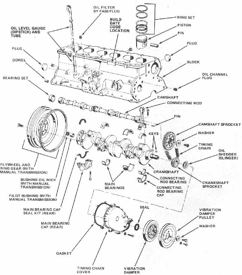
2001 civic engine diagram

D17 rod bearing diagram and codes. Diagrams for the following systems are included.


2000 Honda Accord Drive Belt Replacement Honda Civic Engine 2000 Honda Civic Honda

2001 honda civic engine diagram here you are at our website.

. In 1974 honda added a larger engine to the civic measuring 1237 cubic. 2001 Honda Civic Front Suspension Diagram. Onda Civic 2001 fuse box diagram Year of production.

Engine coolant blower motor relay. Posts Related to 2001 Honda Civic Engine Mount Diagram. 2001 honda civic wiring diagram.

The back of a D17 engine block. AEMPerrin EBCS install diagram for externally gated turbos. Fuse box layout honda civic lx ex si vp dx ex hx gx hybrid.

Nowadays we are delighted to declare we have discovered an awfully interesting niche to be discussed namely 2001 honda civic parts diagram. Find detailed specifications and information for your 2001 Honda Civic Sedan. 1999 2001 2 0l honda cr v ignition system wiring diagram 1997 1998 how do you find the firing order which spark plug wire goes to for a crv and odyssey 1995 2000 orders repair guide autozone car pdf manual fault codes dtc 1996 1 6l civic 06 diagrams distributor drive broke inside engine tech forum discussion i Read More.

Honda Civic Engine Mount Diagram. Home Unlabelled 2001 Civic Engine Diagram - Need A Diagram Of The Engine 02 Civic Ex 2dr Honda Tech Honda Forum Discussion. 2001 honda civic parts diagram - thank you for visiting our website.

At November 04 2021. The location of the fuses in the engine compartment. Dec 3 2015 - 2001 Honda Civic Engine Diagram 01 chartsfree diagram images 2001 honda civic engine diagram car parts download.

Can I get the timing marks 2001 honda civic 17 please. Were is the fuse box on the 1992 honda prelude vti the in car fuse box and wat is the black switch under the steering wheel fuse box access is right beside your. Home Tanpa Label 2001 Civic Engine Diagram.

This video demonstrates the Honda Civic Wiring Diagrams and details of the wiring harness. 2007-2008--Honda--Civic SI--4 Cylinders 20L FI DOHC--33138301. 2001 Honda Civic Engine Diagram 03 chartsfree diagram images 2001 honda civic engine diagram car parts download.

Honda CRV 2001-06 Wiring Diagrams Repair Guide. Power distribution electrical schematic auxiliary fuse holder a fuse 51 2006 fig. 2001 Engine Compartment Fuse Box Number Ampere rating A Circuits protected 1 20 Condenser Fan 2 15 Small Light 3 75 Interior Light 4 20 Cooling Fan 5 10 Hazard 6 15 FI ECU 7 15 Small Light 8 20 ABS FS 9 10 Back.

93 Honda Civic Fuse Box Diagram. Effectively read a wiring diagram one has to. Here is a guide and the diagrams below so you can see how the job is done.

Get your hands on the complete Honda factory workshop software 999 Download now. Many individuals looking for information about 2001 honda civic engine diagram and definitely one of these is. Many individuals looking for details about 2001 honda civic parts diagram and of course one of them is you is.

With this Honda Civic Workshop manual you can perform every job that could be done by Honda garages and mechanics from. Home Tanpa Label 2001 Civic Engine Diagram - Part 1 How To Test The Ignition Coils 2001 2005 1 7l Honda - The location of the fuses in the engine compartment. Find out how to access AutoZones Overall Electrical Wiring Diagram Repair Guide for Toyota Avalon Camry Camry Solara 2001-06.

Honda Civic Workshop Manual L4-18L 2006 Honda - Civic - Repair Guide - 2001. At this time we are excited to declare we have discovered an extremely interesting niche to be pointed out namely 2001 honda civic engine diagram. Free delivery for many products.

1998 Honda Civic Lx Engine Diagram. Onda Civic 2001 fuse box diagram Year of production. Complicated yet efficient catchcan setup for FI.

You use H22 mounts adapt civic wire harness to the f22 f22 half shaft 90-93 intgra axles or you could use h22 half shaft and axles but you have to use one or the The fourth generation Honda Accord spanned the years between 1990-1993 and is commonly called the CB chassis. Honda Civic Wiring Diagram Pdf. 2001 honda civic engine diagram.

2001 Honda Civic Engine Mount Diagram. Honda Prelude Engine Wiring Diagram Honda Civic Engine Diagram pertaining to 2001 Honda Prelude Wiring Diagram by admin Through the thousands of photographs online concerning 2001 Honda Prelude Wiring Diagram we picks the top series having best resolution simply for you all and now this photos is among pictures collections in your best graphics. Changing spark plugs brake fluids oil changes engine rebuilds electrical faults.

To open it push the. 98 Honda Civic Engine Diagram. Get your hands on the complete honda factory workshop software.

7th Generation Honda Civic Em - Engine control module ecm front ignition coils. Special diagnostic tools are required. Wiring HIDs on a two bulb hilow beam Honda setup 04-05 Hondas or 01-03 projectors.

2001 Engine Compartment Fuse Box Number Ampere rating A Circuits protected 1 20 Condenser Fan 2 15 Small Light 3 75 Interior Light 4 20 Cooling Fan 5 10 Hazard 6 15 FI ECU 7 15 Small Light 8 20 ABS FS 9 10 Back Honda Civic fuse box. Simplified return fuel setup diagram. Free Online Service and Repair Manuals for All Models.

2001 honda civic engine diagram - here you are at our website. Found in the Japanese 6th gen AccordTorneo Euro-R. 2001 Civic Engine Diagram - Need A Diagram Of The Engine 02 Civic Ex 2dr Honda Tech Honda Forum Discussion.

2001 engine compartment fuse box number ampere rating a circuits protected 1 20 condenser fan 2 15 small light 3 7 5 interior light 4 20 cooling fan 5 10 hazard 6 15 fi ecu 7 15 small light 8 20 abs f s 9 10 back. The Honda Civic 2001 2003 Misc Documents Wiring Diagrams PDF includes. 2001 honda civic engine diagram 03 chartsfree diagram images 2001 honda civic engine diagram car parts download.

Honda Civic Suspension Diagram. 2001 honda civic ex engine diagram. The diagrams in this section give.

Check out our popular Honda Civic Manuals below. Changing oxygen sensor for a 2000. Honda - Civic - Wiring Diagram - 2001 - 2003 Updated.

D17 Main bearing diagram and codes. Find this Pin and more on Cars Motorcycles by Antony Muhia.

Kamis, 17 Februari 2022

chevy suburban stereo wiring diagram

Switched 12V Yellow. Chevy Wiring A Diagram For 1994 Chevy Suburban Stereo.


30 Awesome 2003 Gmc Yukon Bose Radio Wiring Diagram Chevy Silverado Gmc Yukon Chevy Trailblazer

Left Rear Speaker IMPORTANT - There are two 2 yellow two 2 gray and two 2 brown wires in this harness.

. The connectors are shown with end-on views with. If you want to install a car stereo and save time youll love our Chevrolet stereo wire guide. Radio Antenna Trigger Wire.

Back up lamp power window wiring diagram 1. Check this for 2000 chevrolet silverado c1500 car stereo wiring diagram. Print the wiring diagram off plus use highlighters to trace the signal.

Every Chevrolet stereo wiring diagram contains information from other Chevrolet owners. Pinouts GM Chevrolet Buick Pontiac Saturn Cadillac OEM car audio Amplifiers pinouts. 2003 chevrolet suburban stereo wiring information.

Delco cdr 500 a 4 12 v direct a5 antenna output a6 ilum a7. Left Rear Brown. Each part should be set and connected with other parts in specific manner.

The diagram is surrounded by a alphanumeric loaction grid. All the wires at the connectors have alphanumeric addresses showing where the other end of the wire is located ac cording to the grid. Radio Switched 12V Wire.

Cevrolet Aveo 2007 stereo. Free Schematics 1999 Chevy 2500 Engine Compartment Wiring Diagram 1991 Chevrolet 1500 Pickup Chevrolet Pickup Chevy Chevy Pickups I need a wiring diagram for a 2000 chevy silverado. This information outlines the wires location color and polarity to help you identify the proper connection spots in the vehicle.

Chevy Suburban Stereo Wiring Diagram Wiring Diagram For 1997 Suburban truthaboutforthood com. Free Schematics 1999 Chevy 2500 Engine Compartment Wiring Diagram 1991 Chevrolet 1500 Pickup Chevrolet Pickup Chevy Chevy Pickups I need a wiring diagram for a 2000 chevy silverado. 2005 Chevrolet Astro 2004 Chevrolet Astro 2003 Chevrolet Astro 2002 Chevrolet Astro 2001 Chevrolet Astro 2000 Chevrolet Astro 1999 Chevrolet Astro 1998.

GM 2003-2005 BOSE Amplifier pinout. 55 Awesome Dual Radio Wiring Diagram Marine Radio Car Stereo Car Stereo Systems. 2002 Suburban Stereo Wiring Diagram netbook review com.

30 Fresh Delphi Radio Wiring Diagram Radio Electrical Wiring Diagram Delphi. Left Rear Speaker - 14. 02 suburban radio wiring diagram.

Locate the 12 volt constant wire first. Cevrolet Aveo 2007 radio wiring connector 4. Cevrolet Aveo 2007 radio wiring connector.

Diagram 2003 chevy radio wiring with sub full version hd quality activediagram reverbfestival it chevrolet car stereo audio autoradio connector wire installation schematic. Cevrolet Aveo 2007 radio wiring connector 3. 1 trick that we 2 to printing a similar wiring plan off twice.

Radio wire diagram radio wiring harness radio wire harness stereo wiring color. Cevrolet Aveo 2007 radio wiring connector 5. Class 2 Serial Data Radio Ground Wire.

93 chevy ac wire diagram wiring 1993 5 7 tahoe 1500 actuator gmc k1500 ecm suburban tail light 95 2003 1989 fuse full box 1994 98 z71 harness radio fuel pump circuit tests gm 4 3l 2001 1999 brake lights 1995 yukon engine ftp transmission 2000 dodge durango eda95 schematic 1 96 1998 truck block 1996. WIRING DIAGRAMS DESCRIPTION These diagrams use a new format. Label it or splice to constant wire on aftermarket stereo first.

2002 Suburban Radio Wiring Harness Diagram wiring diagram is a simplified agreeable pictorial representation of an electrical circuit. Left Front Tan. March 31st 2012 Posted in Chevrolet.

2007-2011 Chevrolet Suburban Wiring Diagram. 2000 Chevy Suburban Radio Wiring Diagram abcdstudioinfo. Right Front Light Green.

Chevrolet Captiva 2008 stereo wiring. Silverado Engine Wiring Harness In 2020 Chevy. Left Front - Gray.

1992-93 Chevrolet Suburban Stereo Wiring. 30 Awesome 2003 Gmc Yukon Bose Radio Wiring Diagram Chevy Silverado Gmc Yukon Chevy Trailblazer. 4 x 10 Roof Mount.

Silverado Engine Wiring Harness In 2020 Chevy. Chevrolet Impala 2002 stereo wiring connector. 1997 Suburban Wiring Diagram ImageResizerTool Com.

This video demonstrates the Chevrolet Silverado Complete Wiring Diagrams and details of the wiring harness. Whether your an expert installer or a novice enthusiast with a 1999 Chevrolet Suburban an automotive wiring diagram can save yourself time and headaches. At the car stereo harness connector end view Ask a question.

2004 chevy suburban bose radio wiring diagram. One of the most time consuming tasks with installing a car stereo car radio car speakers car amplifier car navigation or any mobile. 50 Lovely 2002 Chevy Suburban Radio Wiring Diagram In 2020 Chevy Tahoe Chevy Trailblazer Silverado.

4 x 6 Dash. Check fuses if your unable to find 12 volts. Listed below is the vehicle specific wiring diagram for your car alarm remote starter or keyless entry installation into your 2007-2011 Chevrolet Suburban.

Diagrams for the following systems are included. Chevrolet Stereo Wiring Diagrams. Swapping yellow wires will cause damage to any aftermarket stereo.

2001 Chevy Suburban Stereo Wiring Diagram August 12 2021. OEM radio stereo harness pin assignment. Chevrolet Alarm Remote Start and Stereo Wiring.

2002 chevy suburban radio wiring diagram. Delco cdr 500 a 4. Constant 12V Orange.

Cevrolet Aveo 2007 radio wiring connector 2. Back up lamp power window wiring diagram 1. 2002 Chevy Suburban Radio Wiring Diagram 2002 chevy suburban radio wiring diagram Every electric arrangement consists of various distinct pieces.

24 pin GMC 12110244 12110088 15306210 Radio Harness connector. Otherwise the arrangement wont function as it ought to be. Check this for 2000 chevrolet silverado c1500 car stereo wiring diagram.

I have access to about 6 different diagrams for an 02 burb 53. 99 Suburban center and rear speaker wiring HELP Chevy. We support voluntary technician certification.

A wiring diagram is a streamlined traditional pictorial representation of an electric circuit. 1999 Chevrolet Suburban Stereo Wire Diagram. It reveals the components of the.

Right Front - Dark Green. Variety of 2004 silverado bose radio wiring diagram. Please be sure to test all.

Rabu, 16 Februari 2022

chevy truck engine wiring harness

Qty in Cart. Reproduction Wiring Harnesses are complete with original connectors and wire colors for ease of installation.


1996 Gmc Truck C1500 1 2 Ton P U 2wd 5 0l Mfi Ohv 8cyl Repair Guides Wiring Diagrams Wiring Diagrams Au Electrical Diagram Repair Guide Chevy Silverado

Add to wish list.

. We try and make this as easy for you as possible. K5 Blazer Wiring Harness Wiring Diagram Name 1985 Chevy Truck Wiring Diagram. We offer a wide range of Chevrolet wiring harnesses sourced from some of the most trusted manufacturers in the automotive industry.

Classic Industries offers a wide selection of Harnesses for your 1958 Chevrolet Truck. Classic Industries offers a wide selection of Harnesses for your Chevrolet Truck. 1961 Chevy GMC Truck Engine Harness V8.

Our wiring harnesses are brand-new and better than NOS. Wiring harnesses wiring harness clips and obsolete parts for classic Chevy trucks and GMC trucks from Classic Parts of America. Chevy C10 Wiring Harness Complete Wiring Harness Kit - 1960-1966 Chevy Truck Part 500560 1960 - 1966 Chevy C10 Chevy C20 wire harness 500560 american auto wire chevy truck wiring harness Classic Update Series Complete Wiring Kit c10 c20 chevy wire.

Direct fit with original gauge color and connectors with idle stop solenoid. The item 95 CHEVY CORVETTE LT1 ENGINE MOTOR DROPOUT 57L 350 WIRING HARNESS ECU 119K MILE is in sale since Saturday October 30 2021. The new ATO style 18-fuse 29-circuit fuse panel fits in the original location and requires no modifications to firewall.

Your part request will be emailed instantly to a nationwide network of Junkyards. 1974 Fullsize Chevy GMC Truck Engine Harness V8 454 ci With Gauges. 2282022 if ordered today.

Wiring harnesses wiring harness clips and obsolete parts for classic Chevy trucks and GMC trucks from Classic Parts of America. Reproduction engine wiring harness comes complete with the original connectors and wire colors for an easy installation. This item is in the category eBay MotorsParts AccessoriesCar Truck Parts AccessoriesEngines Engine PartsEngines.

000 Home Login Order Status Shipping Return Policy. The seller is thecorvettedepo and is located in Ashley Ohio. There is ample documentation to substantiate this claim.

If you have a broken harness or perhaps suffered an electrical fire you can remedy this problem with a brand new Chevrolet C- and K-Series Truck engine wiring harness. This item can be shipped. Generation ChevyGMC Pickup - 1973-87.

New old stock THE PROBLEM. Our aftermarket wiring harnesses are made from high-grade materials ensuring smooth and reliable performance for many years. Ad Über 80 neue Produkte zum Festpreis.

Our Locator service will help you get a quality engine wiring harness. Factory reproduction of the original engine wiring harness. Chevrolet Truck Parts - Harnesses.

Das ist das neue eBay. Aftermarket Chevrolet C- and K-Series Truck engine wiring harnesses are plug and play so that you can easily get your vehicle back on the road where it belongs. Find the chevy engine wiring harness using our Salvage Parts Locator.

Classic Industries offers Chevrolet Truck Front Lamp Harnesses Chevrolet Truck Engine Wiring Harnesses Chevrolet Truck Underdash Wiring Harnesses Chevrolet Truck Rear Body Lamp Harnesses Chevrolet Truck Universal Gauge Harnesses Chevrolet Truck Air. Follow this step-by-step install. Write a Review Write a Review.

Finde Vehicle Wiring Harness. In addition Wiring Diagram gives you enough time frame by which the assignments are for being completed. Engine Harness V8 wElectric Choke Fits 1981-84 ChevyGMC Truck Rating Name Email Review Subject Comments.

The seller is thecorvettedepo and is located in Ashley Ohio. If your original harness is missing or damaged beyond recognition you may need to purchase a factory assembly manual or a wiring diagram for correct harness routing and wiring diagrams see pages and for manualsWiring diagrams ARE NOT included with reproduction. Factory reproduction of the original engine wiring harness.

Classic Industries offers 1958 Chevrolet Truck Front Lamp Harnesses 1958 Chevrolet Truck Engine Wiring Harnesses 1958 Chevrolet Truck Underdash Wiring Harnesses 1958 Chevrolet Truck Rear Body Lamp Harnesses 1958 Chevrolet Truck. Engine Harness V8 with Electric Choke Fits 1981-84 ChevroletGMC Truck Product Videos. Qty in Cart.

Upgrade your 1953 Chevy trucks wiring harness with American Autowires Classic Update kit for 1947-54 Chevy 3100 trucks. 1958 Chevrolet Truck Parts - Harnesses. 000 Home Login Order Status Shipping Return Policy.

Add to wish list. You may be able to know exactly when the projects should be completed that makes it easier for you personally to correctly control your time and efforts. 1961 Chevy GMC Truck Engine Harness V8 Available for stock and HEI ignition.

You May Also Like. Wiring Harness Factory Fit Front Fuse Block Location Standard Length Dash Harness Only Chevy Camaro Automatic Transmission Each. American Autowire CA01544 - American Autowire Factory-Fit Wiring Harnesses.

Once you fill out the form you are done. 1973-87 A Wiring Harness Designed Specifically for Your Classic Truck. As a matter of fact your vehicles original wiring was only designed to last 10 years before it started to deteriorate.

The item 95 CHEVY CORVETTE LT1 ENGINE MOTOR DROPOUT 57L 350 WIRING HARNESS ECU 119K MILE is in sale since Saturday October 30 2021. We have wiring harnesses for various Chevrolet models such as the Camaro Traverse and Silverado. This item is in the category eBay MotorsParts AccessoriesCar Truck Parts AccessoriesEngines Engine PartsEngines.

BROTHERS Factory Style wiring modules are not only easy to use and install but they also boast the highest quality and provide the exact fitment and functio. Wiring harness will rewire truck from headlights to tail lights and is able to add many options and accessories. Lets face it folks NO automobile manufacturer ever designed a wiring harness to last 40-70 years.

Selasa, 15 Februari 2022

diagram 1988 amc 360 engine

Jeep cj series 304 360 amc engine bracket diagram. AMC Seat Assemblies Section 19.


Technical Data

3 in 1978 the model with 2-door fastback coupe body and V-8 5896 cm3 3598 cui 1045 kW 142 PS 140 hp SAE net offered since September 1977 for North.

. 1971-1986 Jeep CJ5CJ7CJ8 Scrambler 1972-1984 Wagoneer 1974-1983 Cherokee1984-1991 Grand. Engine horsepower and torque curve for AMC Matador Coupe V-8 360 automatic aut. I have a rebuilt amc 360 and need to attach all of the accessories.

Amc Service Repair Manuals Wiring Diagrams - By. AMC V8 Firing Order Application Details. Locations System Sentry Control Module Under RH Side Of Steering Column Throttle Position Sensor - Sluggish Engine Response Throttle Position Sensor.

These specifications were produced in the early seventies. Jeep CJ Series 304 360 AMC engine bracket Diagrams. Sprocket Camshaft for AMC V8 Engine.

1971-1979 Jeep CJ5 w 50L V8-304 Engine. 1978 Jeep CJ Wiring Diagram. Clutch Diagram for Vintage W- V8-304 V8-360 V8-401 Engines.

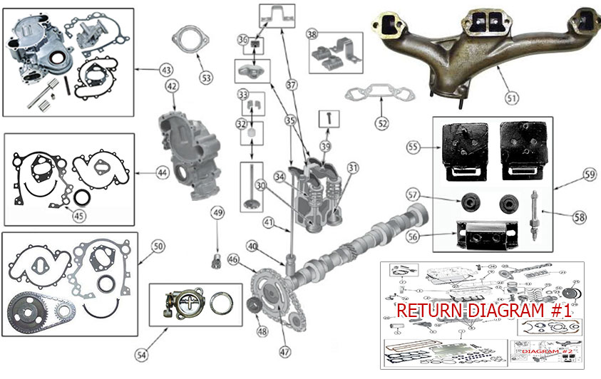
AMC 360 in 85 Grand Wagoneer timing instructions. Jeep Grand Wagoneer 5 9 L 360 Amc 8 Zyl Motor. Click on numbers on images to see the associated products.

I cant find many good pictures online. 1970-1979 Jeep SJ J-Series w 59L V8-360 Engine. This manual contributed by Lindel Easley covers ALL jeep engines including the 71-90 AMC 360.

Add to cart for 2899 Add to wish list Add to compare. Originally Posted by FSJunkie. Add to cart Add to wish list Add to.

1973 AMC Service Manuals PDF spare parts catalog fault codes and wiring diagrams 1973 AMC cars service manuals including. I do not have current numbers at this time. 1978 Jeep CJ Wiring.

1974-1988 Jeep J10 w 59L V8-360 Engine 1974-1988 Jeep J20 w 59L V8-360 Engine 1971-1983 Jeep Wagoneer SJ w 59L V8-360 Engine 1972-1973 Jeep C104 Commando w 50L V8-304 Engine 1984-1991 Jeep Grand Wagoneer SJ w 59L V8-360 Engine. During this procedure if you notice any worn or burnt parts you should replace them before continuing. 1953-1971 CJ Dj Service.

Hornet Matador Gremlin Javelin and Ambassador. AMC Torque Command Transmissions Section 7. Amc V8 Engine Wikipedia from.

There are too many dang parts to this thing. The first design was produced from 1956 through 1967. 1974 1975 Jeep CJ Wiring Diagram.

Im putting together one of the last parts in getting ready for my engine swap. Minggu 19 Desember 2021 The other brackets do not look familiar as amc engine brackets. I have a rebuilt amc 360 and need to attach all of the accessories.

Answer ID 4932 Published 04172018 1022 AM Updated 11122019 0246 PM Was this answer helpful. On LH Side Of Torque Converter Clutch Page 11 Alarm Module. 1972 1973 Jeep CJ Wiring Diagram.

1976 1977 Jeep CJ Wiring Diagram. AMC Suspension Section 11. This was in contrast to the imperials.

Remanufactured Long Block AMC 360 1972-1991-Remanufactured NOT rebuilt. 1 3 5 7 on the driver side. The other brackets do not look familiar as amc engine brackets.

AMC V-8 50L 304 and 59L 360 Engine Parts for Jeep CJs Wagoneer SJ. Diagram 1988 Amc 360 Engine. The AMC V8 may refer to either of two distinct OHV V8 engine designs that were developed and manufactured by American Motors Corporation AMC.

I just need pictures or something. During the 1972 to 1993 model years of. 1976-1979 Jeep CJ7 w 50L V8-304 Engine.

The cylinder bore was 408 inches and the crankshaft stroke was 344 inches. Add to cart for 2899 Add to wish list Add to compare. The engines were used in cars and trucks by AMC Kaiser and International Harvester as well as in marine and stationary applications.

Engine specific production specifications for 360 - 401 engines. Unlike many of the products. And yes there is a difference a big difference.

The AMC 360-cubic inch displacement V-8 engine was an overhead-valve design with two valves one intake and one exhaust per cylinder. Most AMC V8 engines. Senin 06 Desember 2021 Follow along as we complete the budget amc 360 engine build for our 1967 amc.

5 0L V8-304 1971-1981 CJ-5 6 7 8 C104 Commando 5 9L V8-360 1970-1991 SJ J-Series 6 6L V8-401 1971-1979 SJ J-Series map imageMapResize. AMC service repair manuals free download 1973 AMC Technical Service Manual AMC Axle and Propellor Shaft Section 9 AMC Bodies-Panels-Subassemblies Section 13 AMC Brakes and Wheels Section 8. 1972-1973 Jeep C104 Commando w 50L V8-304 Engine.

AMC Weather Eye and Command Air System Section 12A. AMC Instrument Panel Section 18. The bore spacing on the engine block was 475 inches center-to-center.

The Warner Overdrive TSM was sent to me by Larry Stevens. Electronic fuel injection finally came to the 318 and the 39 v6 based on it in the 1988 dodge trucks bu tnot cars. Diagram 1988 Amc 360 Engine.

Disc Clutch 9995. The normal oil pressure for this engine is 46 pounds per square inch. AMC Harness Routing and Wiring Diagrams Section 21.

JC AMC 360 in 85 Grand Wagoneer timing instructions. The following instructions sound very complicated and intimidating but this is a very easy procedure if you follow the instructions and do things very carefully and slowly. 1976-1979 Jeep Wagoneer SJ w 59L or 66L Engine 1965-1986 SJ J-Series w 42L Engine 1981-1983 CJ5 w 42L Engine 1981-1986 CJ7 w 42L Engine 1981-1986 CJ8 w 42L Engine.

1974-1988 Jeep J10 w 59L V8-360 Engine 1974-1988 Jeep J20 w 59L V8-360 Engine 1971-1983 Jeep Wagoneer SJ w 59L V8-360 Engine 1972-1973 Jeep C104 Commando w 50L V8-304 Engine 1984-1991 Jeep Grand Wagoneer SJ w 59L V8-360 Engine. AMC Harness Routing and Wiring Diagrams Section 21 AMC Instrument Panel Section 18 AMC Seat Assemblies Section 19 AMC Six-Cylinder Engine Section 1A AMC Suspension Section 11 AMC Torque Command Transmissions Section 7 AMC V-8 Engine 304 360 401 Section 1B AMC Weather Eye and Command Air System Section 12A AMC Windshield. Borg Warner Overdrive Unit Technical Service Manual for some Jeep CJs according to Larry Stevens.

Jc amc 360 in 85 grand wagoneer timing instructions. 2 4 6 8 on the passenger side. Part Diagrams Next Icon.

View this page as large as possible and under high resolution for best results. AMC V-8 Engine 304 360 401 Section 1B. Use our exploded images to find.

AMC Six-Cylinder Engine Section 1A. 1971-1975 Jeep CJ6 w 50L V8-304 Engine. During this procedure if you notice any worn or burnt parts you should replace them before continuing.

All Technical Service Bulletins Throttle Position Sensor - Sluggish Engine Response Models 1987-1988 Jeep Models With 40L Engine 1986-1988 Jeep Models With. I need pictures or info on how the heck the brackets all work and go together for the alternator on a 1987 grand waggy. The following instructions sound very complicated and intimidating but this is a very easy procedure if you follow the instructions and do things very carefully and slowly.

Marneaus is now officially my idol. AMC V-8 50L 304 and 59L 360 Engine Parts for Jeep CJs Wagoneer SJ. I have 3 wires coming from the dist.

The Full 1953 - 1971 Jeep CJ Dj Service Manual was sent to me by Noah Freibert. Firing Order AMC 360cid. Jeep cj series 304 360 amc engine bracket diagrams.

Senin, 14 Februari 2022

brake proportioning valve diagram

Tilton Engineerings patented adjustable hydraulic brake proportioning valve enables the driver or a crew member to adjust the brake-force to a particular wheel or wheels. Therefore the brake proportioning valve as we know it today hadnt even come onto the Ford truck scene yet.


Brake System Designing Made Simple We Ll Take Out The Confusion About What Those Parts Do And How To Use Them Brake System Car Brake System Brake

A brake warning light to detect a loss in pressure Proportioning Valve Plumbing Diagram.

. The proportioning valve determines the percentages of brake fluid directed to the front and rear brakes to ensure safe braking. In a moderate braking situation line pressure being generated by the master cylinder is less extreme and therefore. 2 Start with the valve in the full increase position by turning the knob all the way.

The valve stops the flow or pressure of brake fluid to the rear drum brakes during every heavy braking or emergency stops. This diagram illustrates the 2 most common types of fittings used in street rod brake systems. Brake Line and Proportioning Valve Install Tips F100 Episode 457 AutorestomodWe install a set of NPD brake lines and a Brake Proportioning valve on our F100.

The proportioning valve in a vehicles brake system provides a way to control how much and when brake pressure is applied to each axle set of the brake system. Unlike a metering valve. OEM SUZUKI SAMURAI REAR BRAKE PROPORTIONING VALVE.

This diagram from the Ford Truck Shop Manual isnt 100 accurate as the factory piece actually used has 5 ports plus the switch port as opposed to the 4-port Mustang version showed here. The benefit of having a proportioning valve in the system. Proportioning Valve Kit Build Sheet 1.

The first is a 90 degree bend with one leg longer than the other. PV2PV4 Proportioning Valve KIT Installation Instructions left Side Kit used for example but instructions apply to all kits Included in this Kit. The brake line.

InstallatI on Select either the frame or bulkhead mounting style and follow the steps below. Located between the master cylinder and the rest of the brake system this component is the key to safe reliable brake system operation in all conditions. Select a location for frame mounting the proportioning valve that allows easy access to the adjusting handleknob.

Brake Proportioning Valve - Repair or Replace. The brake proportioning valve is a metering device that equalizes the pressure between the front and rear brakes. If the pressure was not proportioned the disc brakes would engage before the drum brakes when you depress the brake pedal.

Add to wish list Add to compare. What the Proportioning Valve does and when it actually works is one of the biggest misunderstandings in a Combination Valve. If your proportioning valve fails you may notice a brake fluid leak soft pedal or inefficient or grabby brakes.

A spool or stem slides back and forth. Brake Proportioning Valve Diagram. Guaranteed Lowest Price Well match or beat any price Part.

There are two proportioning valve lines that connect to the master cylinder provided in our kits. Proportioning Valve Plumbing The most common proportioning valve plumbing is shown below. From the T fitting the front lines are then split off to the left and right calipers.

The proportioning valve can also be used effectively with dual master cylinder systems. Ad Broad selection of PPS grades for automotive and electronics components. My problem is I cant find any parts or relevant material for this specific valve.

Note that Figures B and C both generate 950 psi of rear brake-line pressure when the front brake-line pressure is at 2000 psi However one can also see that Type C systemsthose that use. The inner workings of an adjustable proportioning valve are relatively simple but deceptively complex. Ad Broad selection of PPS grades for automotive and electronics components.

Call or text us with your questi. This diagram shows a typical street rod brake system. Satisfaction Guaranteed No hassle return policy.

Make sure that the location allows room for the hydraulic lines and access for. If I give my brakes any more than light even pressure the rear wheels lock up. Looking at the diagrams one can see that it is possible to design both a Type B system and a Type C system that ultimately give the same brake balance at the point of maximum deceleration.

However the principle is the same. One component often overlooked is the proportioning valve. An alternative plumbing method is to plug off the top front line and have the bottom front line go to a T fitting.

Brake proportioning valves are the parts of a vehicles brake system that limit the amount of pressure reaching the rear brakes which helps to prevent rear wheel lock-up allowing you to stop your vehicle more safely and efficiently. This line must be oriented with the long leg connected into the front top hole of the proportioning valve and the short end in the front hole. Brake Warning Light 3.

Whether your vehicle has rear disc brakes or drum brakes the rear brakes require less pressure than the. The light rugged valve may be bulkhead or panel-mounted. Home Diagrams For Suzuki Brake Parts OEM SUZUKI SAMURAI REAR BRAKE PROPORTIONING VALVE.

Proportioning valves were used before ABS to divert brake force to the front and rear brakes. A 2 PSI residual pressure valve RPV is needed in the disc brake circuit and a 10 PSI RPV is required in the drum brake circuit as well as an adjustable proportioning valve APV. All proportioning valve configurations for Camaro Firebird and Nova along with how these valves change prevent brake lines.

1 The proportioning valve in the Prop Block will be used to adjust the rear brake pressure of the vehicleThe objective is to balance the pressure of the rear brakes to the front so that under hard braking the rear brakes do not lock up before the fronts. Contact us for a price. From what I can find this usually means proportioning valve issues and when I looked at my valve its condition seems to support this theory.

Bob Wilson owner of RJ Restorations explains how the proportioning valve functions and demonstrates the process of rebuilding one. Brake Proportioning Valve INSTALLATION INSTRUCTIONS 98-1261. Its like it doesnt exist.

Otherwise the rear brakes lock up and skid receiving too much pressure from the master cylinder. Inside is a piston with less effective surface area at. Disc brake pads are normally in contact with the disc while the drum brake shoes are normally not in contact with the drum.

1 Proportioning Valve 2 Pre-bent lines 1 Brake light wiring harness 1 Mounting bracket 2 516-18 bolts 2 washers-flat 2 washers-split locking Proper operation of your brakes is essential for your safety and the safety of others. The proportioning valve is often one of the less understood. The Proportioning Valve part of the Combination Valve seen above and labeled as A is used to control the rear brakes.

The proportioning valve lets you adjust the rear brake pressure to account for different tires front to rear weight bias and the effectiveness of rear disc or drum brakes. A Proportioning valve is required on vehicles that have disc brakes on the front wheels and drum brakes on the rear wheels.